Part 3 in my Exploring Wisblock series
Source code for this example can be found here.
The RAK11310 Core module is based on the RP2040, the microcontroller used in the Raspberry Pi Pico. This is a dual core Arm Cortex-M0+ processor so I was curious to see if the second core can be used in the Wisblock environment. This would be particularly useful for me as I would like to do data acquisition and processing on one core and display and communications on the other.
Although my previous attempts to use the Arduino IDE with the RAK11310 were not successful, I had not completely given up since at times I was able to get it working. So I sent an inquiry to the RAK Wireless forum inquiring whether there is support for the second core. The RAK Wireless forum is an excellent resource and inquiries are answered promptly and informatively. Bernd Giesecke provided background research and example code showing that the ArduinoCore-mbed BSP does not support the RP2040 second core.
I had previously set up a couple of Raspberry Pi Picos by following the excellent tutorial by Shawn Hymel (here) to set breakpoints in Visual Studio Code and display print statements on a serial terminal in Windows. Since the RAK11310 exposes the SWD pins I thought it might be possible to interactively debug the RAK11310 in Visual Studio. Unfortunately the RAK11310 does not seem to be compatible with picoprobe and the GDB terminal indicated “DAP init failed”.
It turns out that even the native Pico picoprobe debugging in Visual Studio Code does not seem to work with multicore. Whenever I try it the boot loader code stops GDB. But at least picoprobe shows print statements through the USB serial connection, which I can display in puTTY.
So back to the RAK11310 – without print statements showing up through the USB serial connection and no Visual Studio debugger support, development looks pretty challenging. Serial display of print statements is one of the really nice things in the Arduino IDE (besides all the readily available libraries for almost any sensor). So if I am going to do RP2040 multicore development on the RAK11310 I need to at least be able to display print statements from both cores.
the RAK11310 has a boot button which I presume is identical to the boot button on the Raspberry Pi Pico. When you press and hold this button while plugging in the USB cable to your computer a new file explorer opens that has the familiar INDEX.HTM and INFO_UF2.TXT files that you see on a Raspberry Pi Pico. And dropping your compiled uf2 file in this folder reboots the RAK11310 and starts your program. The RAK19007 base board exposes a few pins from the RAK11310 including TX1 and RX1 which presumably come from the RP2040 UART1. The RAK19001 base board exposes most pins from the RAK11310 including RX0, TX0, RX1 and TX1. The Raspberry Pi Pico SDK sends print statement output to UART0 and the SDK provides a uart_puts command that allows you to specify either UART0 or UART1. So it appears that print statements should be easy to see using a serial terminal.
For me the easiest way to do this is using a Raspberry Pi Nano with minicom installed. A simple connection of ground and the Wisblock TXx to RP Nano RXD pin and “minicom -D /dev/ttyS0” should work as a simple debug output. So I wrote a very simple multicore blink program to try out the print statements:
#include <stdio.h>
#include "pico/stdlib.h"
#include "D:\\Pico\\pico-sdk\\src\\rp2_common\\pico_multicore\\include\\pico\\multicore.h"
#define LED_GREEN 23
#define LED_BLUE 24
#define IO1 6
#define IO2 22
#define UART1TX 4
#define UART1Rx 5
//this function will execute on core1
void core1_blink() {
//initialize pin, and set to output
gpio_init(LED_BLUE);
gpio_set_dir(LED_BLUE, GPIO_OUT);
// create infinite loop, which will toggle the green on-board LED with 333ms delays
while(1) {
printf("blinking core 1\r\n");
gpio_put(LED_BLUE, 1);
sleep_ms(333);
gpio_put(LED_BLUE, 0);
sleep_ms(333);
gpio_put(LED_BLUE, 1);
sleep_ms(333);
gpio_put(LED_BLUE, 0);
sleep_ms(1000);
}
}
int main() {
stdio_init_all();
multicore_launch_core1(core1_blink);
gpio_init(LED_GREEN);
gpio_set_dir(LED_GREEN, GPIO_OUT);
gpio_init(IO1);
gpio_set_dir(IO1, GPIO_OUT);
gpio_init(IO2);
gpio_set_dir(IO2, GPIO_OUT);
uart_init(uart1, 115200);
gpio_set_function(UART1TX, GPIO_FUNC_UART);
gpio_set_function(UART1Rx, GPIO_FUNC_UART);
while (1) {
printf("blinking core 0\r\n");
gpio_put(LED_GREEN, 1);
gpio_put(IO1, 1);
gpio_put(IO2, 1);
uart_puts(uart1, "blinking uart 1!\r\n");
sleep_ms(250);
gpio_put(LED_GREEN, 0);
gpio_put(IO1, 0);
gpio_put(IO2, 0);
sleep_ms(250);
}
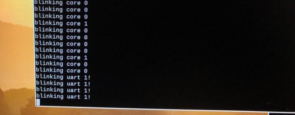
}And there you go – build a RP2040 multicore program in Visual Studio Code using the Raspberry Pi Pico SDK and display serial debug messages from both cores. The screen shot at the top shows the output first from the printf statements on both cores which I presume would go to UART0 but in fact come from the RAK19001 TX1 pin. Moving the RAK19001 TX1 to TX0 I get the uart_puts statement. Very odd that UART0 would be connected to what is labeled TX1 and UART1 is connected to what is labelled TX0.
Leave a Reply
You must be logged in to post a comment.