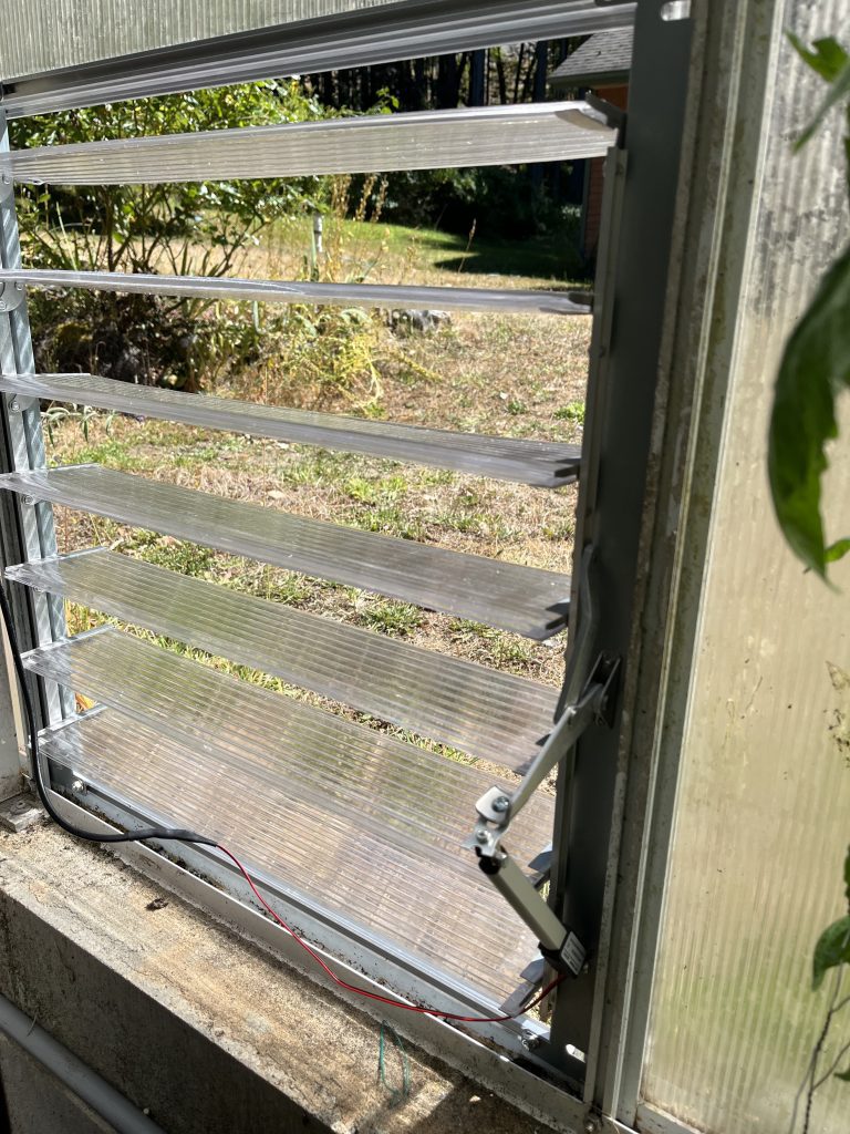
I have a large greenhouse with a fan and vents that are operated by a mechanical thermostat. The greenhouse also has pneumatic vents on the roof. However during the summer these are not sufficient. Also the existing vents are only activated when the fan motor is on as they are on the same circuit. Therefore I added extra vents on opposite walls of the greenhouse to allow extra venting and a cross breize. These are manually operated vents to which I added actuators and a controller to open and close the actuators.
Vents
The vents are Canopia – Palram Side Louver Greenhouse Window which I purchased from Home Depot for C$139. My greenhouse is not that brand but they are fairly generic vents (24 inch) and I was able to fit them without much trouble.
Actuators
The linear actuators are 2025 Trend DC 12V Waterproof IP54 Mini Linear Actuator 100 mm Stroke Electric Linear Motor Window Opener 30 mm/S Speed that I ordered from Ali Express for around C$20 plus C$3 shipping. These seem to be very common devices that a number of Ali Express stores sell. They are two-wire devices that have cut-off switches when the actuator is fully open or fully closed. Reversing the direction of the motor requires reversing the voltage polarity on the two wires.
Controller
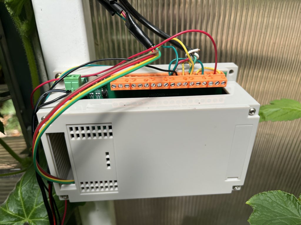
The controller is a Kincony KC868-A6 Smart Home Assistant Relay Switch DIY Module that I got on Ali Express for C$28 plus C$20 shipping. This is a ESP32 C6 based controller with 6 output relays, a number of general purpose ports, I2C and serial interfaces and a socket for a SSD1306 OLED display.
Temperature Sensor
The temperature and humidity sensor is a SHT30 sensor that I got on Ali Express for C$11. This is a fairly generic I2C sensor and any SHT3X based sensor will work.
Software
This project was built using the Espressif ESP-IDT development platform. I use this rather than Arduino because it gives me more granular control of the ESP32. I have a number of other projects, some of which needed features I could not find supported in Arduino and at this point I’ve got past the ESP-IDF learning curve so it’s a more natural environment for me. I can appreciate that this is not everyone’s preference but I’m sure the code could be ported to Arduino.
Features
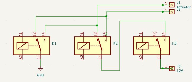
The main feature of the project is the ability to open and close the vents based on threshold temperatures. I have set a separate open and close temperature threshold to provide some hysteresis. By default these are 28 degrees C to open and 25 degrees C to close. When the controller is powered on it closes the actuator so it is in a known state. In order to reverse the voltage polarity to change the direction of the actuator three relays needed to be used. Two of these actually control the voltage polarity and one disables the input voltage to prevent short-circuiting the power supply if the relays operate at different rates. This is the circuit diagram for the relay connections:
In addition the controller sends ESP Now messages to a gateway with the current temperature, humidity and state of the vents.
There is a SSD1306 OLED display that also displays the temperature, humidity and state of the vents but that is mainly for development since the Kincony controller case hides it and it is too bright in the greenhouse to read it.
Algorithm
The software is fairly simple – initialize the system and in a loop check the temperature, decide if the vents need to be opened or closed, display the state, send the state using ESP Now, wait 5 seconds and loop.
The main complication is controlling the relays. In order to preserve IO pins Kincony uses the I2C addressable IO expander PFC8574. To set the relay positions all relays are set at once by writing to a register in the PFC8574. Inputs are handled the same way. The lowest three bits control the three relays. Bit 0 is relay K1 in the circuit diagram, bit 1 is K2 and bit 3 is K3. To extend the actuator, the motor is disabled by sending 0x00 then the motor is enabled with forward direction by sending 0x01. To retract the actuator 0x06 is send to set the direction and disable the motor then 0x07 is sent to set the direction and enable the motor.
Wiring
Here is a diagram of how the relays are wired:
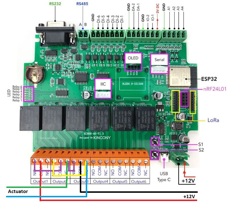
I use two separate 12V power adapters to ensure that the any voltage drop caused by the actuators moving doesn’t affect the controller but I’m sure you could use a singe (heftier) 12V power supply than the small AC adapters I had lying around.
Source code is available in my Git repository