Part 4 in my Exploring WisBlock Series – Read Accelerometer Data on Core 1
Source code for this example can be found here.
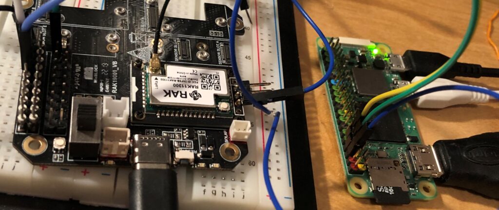
My goal in this series of articles has been to develop a device that could read and process accelerometer data on one core of a RP2040 microcontroller and display and communicate the output on the other core. Originally I considered using a Raspberry Pi Pico but my attention turned to the RAK Wireless Wisblock development systems since they provide a wide variety of easily integrated components for a reasonable price. After various challenges with the software development environment I was able to use Visual Studio Code to develop multi-core software and view print statements on an attached Raspberry Pi Nano. So now the last step is to read accelerometer data on core 1 of the RP2040 based RAK11310.
There are a few accelerometer boards offered for Wisblock base boards, but I chose the LIS3DH based RAK1904. This board uses I2C to communicate and offers a FIFO buffer mode, but for this initial experiment I will simply read the accelerometer to prove that it is accessible from core 1.
Normally people would use the Arduino IDE with the Sparkfun LIS3DH library. But since that will not work in a multicore environment I needed to find the equivalent library from the Raspberry Pi Pico SDK. Fortunately there is a group of I2C examples that include the LIS3DH. Note that the example program lis3dh_i2s.c contains a typo – the TEMP_CFG_REG is 0x1F, not 0xC0.
Running this program as is will not work on the RAK11310 because the I2C channel being used is incorrect. Looking at the circuit diagrams for the RAK19001 base board and RAK11310 as well as the pin definitions for the RAK1904 accelerometer it is apparent that the accelerometer board uses I2C1. Again looking at the RAK11310 circuit diagram, I2C1 is (as expected) connected to GPIO2 and GPIO3. With this simple change and running the sample code on core 1 it can be seen that it is very easy to acquire accelerometer data on core 1.
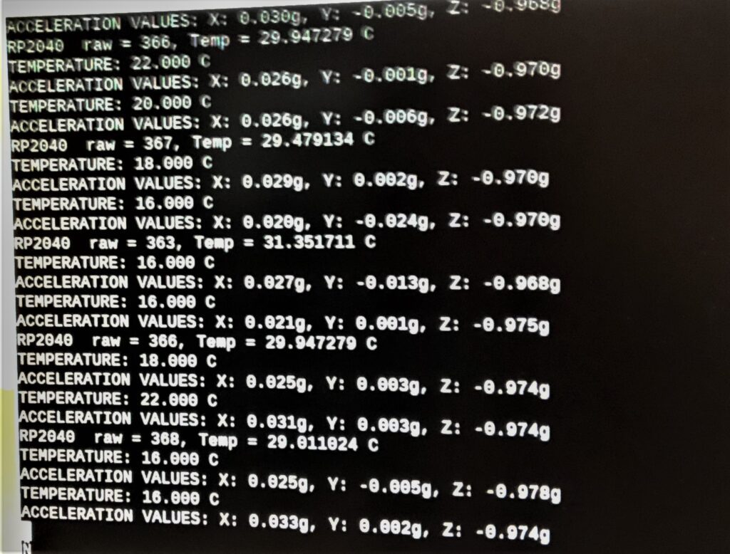
When I was reading the temperature data from the LIS3DH using the example code I noticed that the values were way off and varied quite a bit but usually around 10. The LIS3DH documentation is not very specific about how to use data from the A2D temperature channel other than to indicate that one bit value is one degree C. So for comparison I read the internal RP2040 temperature sensor, according to a tutorial from here. This provided very reasonable values. The lis3dh_i2c.c example divides the raw temperature value by 64 but dividing by 32 gives a more realistic value. I’ve used that but still the values vary and are not very accurate. If you need temperature values, use the internal RP2040 sensor rather than the LIS3DH sensor.
Below is the code that I used as well as a screen shot of the output.
/**
* Copyright (c) 2020 Raspberry Pi (Trading) Ltd.
*
* SPDX-License-Identifier: BSD-3-Clause
*/
#include <stdio.h>
#include <string.h>
#include "pico/stdlib.h"
#include "pico/binary_info.h"
#include "hardware/i2c.h"
#include "hardware/adc.h"
//#include "pico/multicore.h"
#include "D:\\Pico\\pico-sdk\\src\\rp2_common\\pico_multicore\\include\\pico\\multicore.h"
/* Example code to talk to a LIS3DH Mini GPS module.
This example reads data from all 3 axes of the accelerometer and uses an auxillary ADC to output temperature values.
*/
#define LED_GREEN 23
// By default this device is on bus address 0x18
const int ADDRESS = 0x18;
const uint8_t TEMP_CFG_REG = 0x1F;
const uint8_t CTRL_REG_1 = 0x20;
const uint8_t CTRL_REG_2 = 0x21;
const uint8_t CTRL_REG_3 = 0x22;
const uint8_t CTRL_REG_4 = 0x23;
const uint8_t CTRL_REG_6 = 0x25;
const uint8_t WHO_AM_I = 0x0F;
const uint8_t OUT_T_L = 0x0C; // 16 bit resolution
const uint8_t OUT_T_H = 0x0D; // 16 bit resolution
const uint8_t OUT_T = 0x26; // 8 bit resolution
const uint8_t OUT_X_L = 0x28;
const uint8_t OUT_X_H = 0x29;
const uint8_t OUT_Y_L = 0x2A;
const uint8_t OUT_Y_H = 0x2B;
const uint8_t OUT_Z_L = 0x2C;
const uint8_t OUT_Z_H = 0x2D;
//const uint8_t TEMP_CFG_REG = 0xC0;
#define i2c_rak i2c1
const uint I2C0SDA = 20;
const uint I2C0SCL = 21;
const uint I2C1SDA = 2;
const uint I2C1SCL = 3;
void lis3dh_init() {
uint8_t buf[2];
buf[0] = TEMP_CFG_REG;
// enable temperature sensor
buf[1] = 0xC0;
i2c_write_blocking(i2c_rak, ADDRESS, buf, 2, false);
buf[0] = CTRL_REG_1;
// 200 Hz high performance mode
buf[1] = 0x67;
i2c_write_blocking(i2c_rak, ADDRESS, buf, 2, false);
buf[0] = CTRL_REG_4;
// +/- 2g, high resolution
// Turn block data update on (for temperature sensing)
buf[1] = 0x88;
i2c_write_blocking(i2c_rak, ADDRESS, buf, 2, false);
// Configure ADC on RP2040 to read its temperature sensor
adc_init();
adc_set_temp_sensor_enabled(true);
adc_select_input(4);
}
void lis3dh_calc_value(uint16_t raw_value, float *final_value, bool isAccel) {
// Convert with respect to the value being temperature or acceleration reading
float scaling;
float senstivity = 0.004f; // g per unit
if (isAccel == true) {
scaling = 64 / senstivity;
} else {
scaling = 32;
// scaling = 64;
}
// raw_value is signed
*final_value = (float) ((int16_t) raw_value) / scaling;
}
void lis3dh_read_data(uint8_t reg, float *final_value, bool IsAccel) {
// Read two bytes of data and store in a 16 bit data structure
uint8_t lsb;
uint8_t msb;
uint16_t raw_accel;
i2c_write_blocking(i2c_rak, ADDRESS, ®, 1, true);
int numRead = i2c_read_blocking(i2c_rak, ADDRESS, &lsb, 1, false);
if (numRead == PICO_ERROR_GENERIC)
puts("No device present");
reg |= 0x01;
i2c_write_blocking(i2c_rak, ADDRESS, ®, 1, true);
numRead = i2c_read_blocking(i2c_rak, ADDRESS, &msb, 1, false);
if (numRead == PICO_ERROR_GENERIC)
puts("No device present");
raw_accel = (msb << 8) | lsb;
// printf("Raw data %x\n", raw_accel);
lis3dh_calc_value(raw_accel, final_value, IsAccel);
}
uint8_t who_am_I()
{
uint8_t val;
uint8_t reg = WHO_AM_I;
int numWritten = i2c_write_blocking(i2c_rak, ADDRESS, ®, 1, true);
if (numWritten == PICO_ERROR_GENERIC)
puts("No device present");
int numRead = i2c_read_blocking(i2c_rak, ADDRESS, &val, 1, false);
if (numRead == PICO_ERROR_GENERIC)
puts("No device present");
return val;
}
void core1_accel() {
puts("Initializing I2C");
// This example will use I2C0 on the default SDA and SCL pins (4, 5 on a Pico)
uint res = i2c_init(i2c_rak, 400 * 1000);
printf("I2C rate is %d\n", res);
gpio_set_function(I2C1SDA, GPIO_FUNC_I2C);
gpio_set_function(I2C1SCL, GPIO_FUNC_I2C);
gpio_pull_up(I2C1SDA);
gpio_pull_up(I2C1SCL);
float x_accel, y_accel, z_accel, temp;
printf("Hello, LIS3DH %x! Reading raw data from registers...\n", who_am_I());
sleep_ms(2000);
lis3dh_init();
while (1) {
lis3dh_read_data(OUT_X_L, &x_accel, true);
lis3dh_read_data(OUT_Y_L, &y_accel, true);
lis3dh_read_data(OUT_Z_L, &z_accel, true);
lis3dh_read_data(OUT_T_L, &temp, false);
// Display data
printf("TEMPERATURE: %.3f C\n", temp);
// Acceleration is read as a multiple of g (gravitational acceleration on the Earth's surface)
printf("ACCELERATION VALUES: X: %.3fg, Y: %.3fg, Z: %.3fg\n", x_accel, y_accel, z_accel);
sleep_ms(500);
// Clear terminal
//printf("\e[1;1H\e[2J");
}
}
int main() {
stdio_init_all();
multicore_launch_core1(core1_accel);
gpio_init(LED_GREEN);
gpio_set_dir(LED_GREEN, GPIO_OUT);
while (1) {
// read the internal temperature sensor
uint16_t raw = adc_read();
const float conversion_factor = 3.3f / (1<<12);
float result = raw * conversion_factor;
float temp = 27 - (result -0.706)/0.001721;
printf("RP2040 raw = %x, Temp = %f C\n", raw, temp);
sleep_ms(1000);
}
return 0;
}
Leave a Reply
You must be logged in to post a comment.